1-click AWS Deployment 1-click Azure Deployment 1-click Google Deployment
Overview
Visual Studio Community edition was announced on 12 November 2014, as a new free version, with similar functionality to Visual Studio Professional. Prior to this date, the only free editions of Visual Studio were the feature-limited Express variants. Unlike the Express variants, Visual Studio Community supports multiple languages, and provides support for extensions. Individual developers have no restrictions on their use of the Community edition. The following uses also allow unlimited usage: contributing to Open Source projects, academic research, in a classroom learning environment and for developing and testing device drivers for the Windows operating system. All other use by an organization depends on whether you are classified as an Enterprise (more than 250 employees or more than 1 million USD in annual revenue, per Microsoft).] Non-Enterprises may use up to 5 copies without restriction, user number 6 and higher require a commercial license; Enterprise organizations require a commercial license for use outside of the noted exceptions.Visual Studio Community is oriented towards individual developers and small teams
Understanding the Visual Studio Architectural Tools
As you will quickly see, like the Dependency Graph and Layer Diagrams, the UML diagrams are not static. The UML Diagrams are a great way to support Agile Planning through their integration with Visual Studio Team Foundation Server. There five UML 2.0 Compliant Diagrams that ship with Visual Studio Ultimate are:
- Use Case: Illustrates the actors and their interactions with the system
- Class: Illustrates data types that make up the system and the relationships amongst those types
- Sequence: Illustrates the sequence of messages between classes, components, subsystems, and actors
- Activity: Illustrates a business or software process as a series of actions. The system will be capable of performing these actions. Actors and software components are capable of performing these actions.
- Component: Illustrates, in a high-level fashion, the physical parts of a software system.
Collectively, these diagrams illustrate what your problem domain is and what makes up the various elements that comprise the solution to the problem. There are two points to consider before moving forward. The first is to keep pragmatism in mind. You don’t need to use all of these diagrams all the time to be successful. Like anything new, incorporate additions to your toolbox gradually. Second, this article is but a brief introduction. The UML Diagraming tools presented in this article are very feature-rich. The following are good resources for more information on these tools:
- Visual Studio Architecture Guide:
- Modeling the Application (MSDN):
- Clint Edmonson’s Channel 9 Videos:
The Problem Domain: Authentication
To illustrate the UML Diagrams that make up the models, I’ll focus on one aspect of a larger system: authentication and logging into the system with one of four providers:
- Microsoft
The process is:
- The user navigates to the system via a Web browser.
- The user selects the authentication provider (Facebook, Twitter, Google or Microsoft).
- The user logs into the selected provider.
- The user authorizes the system with the provider.
- The user is re-directed back to the system.
- The user is now authenticated and is now logged into the system.
In any model, the one thing you want to avoid is “Boiling the ocean.” In other words, you want to be very focused on a specific feature. If you encompass too much, you take on many risks, including:
- Missing entire features
- Missing functionality for a specific feature
- Software doesn’t follow the S.O.L.I.D. Principles and, as a consequence, is difficult and costly to maintain
Example: logging into the system. As you’ll see, even this one feature has a number of elements that have to be individually tracked and developed. Because the diagrams will focus on this one feature, you avoid the risks enumerated in the previous list. Mel Gibson’s quote in the 2000 movie Patriot conveys the concept nicely: “Aim small, miss small.”
UML: A Brief Primer
If you aren’t familiar with the Unified Modeling Language (UML), there are many resources available to get your knowledge jumpstarted:
- Mike Erickson’s Pluralsight Introduction to UML Course:
- IBM’s UML Basics:
- UML Distilled, Third Edition, Martin Fowler:
As the name implies, UML represents the unification of three different notations:
- Booch Method
- Object Modeling Technique (OMT)
- Object Oriented Software Engineering (OOSE)
UML was first developed in the 1990s by Grady Booch, Ivar Jacobson, and James Rumbaugh during their tenure at Rational Software. Some 20 years later, UML has gone beyond the strict boundaries of Object Oriented Software. UML 2.X now covers business process design as well as data and business modeling. UML’s purpose is simple: to provide a consistent and generally accepted method to model and visualize system, software, and business-process design. Since 2010, Visual Studio has included UML modeling tools as part of the Visual Studio Ultimate product.
In any model, the one thing you want to avoid is “Boiling the ocean.” In other words, you want to be very focused on a specific feature.
Use Case Diagram
Before you can build your first diagram, you first need to create a modeling project. Figure 1 illustrates that process.
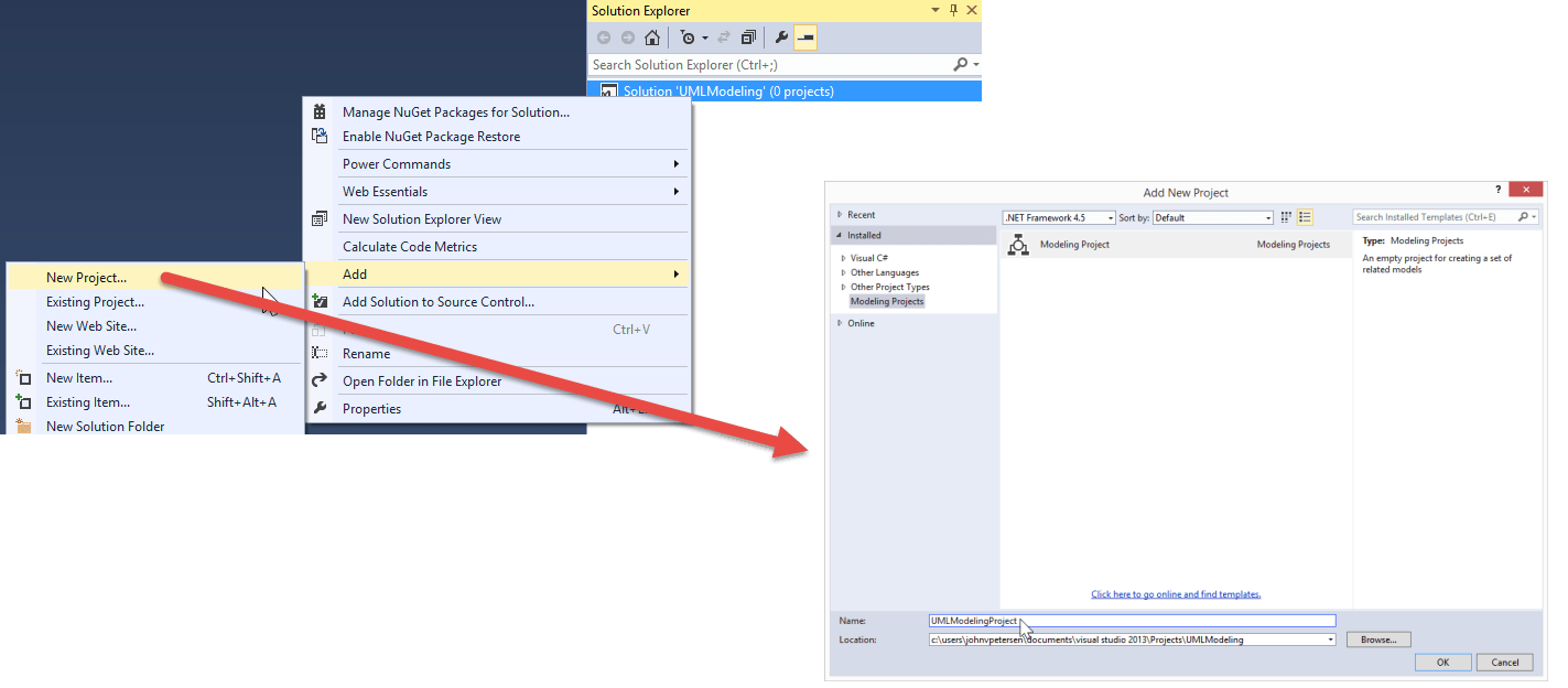
Figure 2 illustrates how to add a new UML Use Case Diagram to the new UMLModeling Project.

Figure 3 illustrates the UML Use Case Diagram Design Surface.

A UML Use Case Diagram illustrates the system, who uses it, and what the user can do with the system. In a Use Case Diagram, users are called Actors. Actors interact with Systems via Use Cases that comprise what the system can do. Not all actors are alike. For example, a customer service representative can look up orders for any customer. An individual customer can only look up their own orders. Each one, the customer service rep and the customer, are actors that interact with the system. Both can look up that specific customer’s orders. The customer service rep however, has extended functionality to see any order. That extended functionality may be manifested as a special menu option or hyperlink on an HTML page. That, however, is an implementation detail and one you aren’t interested in yet. Now is the time to capture what the system can do and who can interact with the system. Figure 4 illustrates a simple use case diagram.

Figure 4 shows one feature of one system. That feature within the system is comprised of four use cases, one each for Facebook, Twitter, Google and Microsoft. Those four use cases are generalized to a common Login/Authenticate use case. Note that the Customer Actor interacts with the system via the four use cases. You also have the ability to associate comments with any aspect of a diagram.
This use case diagram is simple, but nevertheless, conveys a lot of information about the functions the system needs to possess and who needs access to those functions. Note again that the questions of what and who are addressed, not the question of how.
ALM stands for Application Lifecycle Management, which is the process of managing the entire application lifecycle, including requirements gathering, estimation, development, testing, building, deploying, etc. Visual Studio Team Foundation Server (TFS) is one of many tools that support ALM and, as the name implies, is tightly integrated into the Visual Studio IDE. Use case diagrams are an excellent tool to gather requirements. Figure 5 and Figure6 illustrate how the Visual Studio architectural tools support TFS and, as a result, support ALM.


Once you have linked to a work item, you can view linked work items from within the diagram. Figure 7 illustrates this function.

Once a Product Backlog Item is added to a Sprint and becomes a Sprint Backlog Item, the team will associate tasks to implement the feature described in the backlog item. In a Sprint, source code artifacts are created and as they’re checked in, the tasks are associated with those source code commits. If you think about that for a moment, you’ll realize that TFS provides seamless linkage between business requirements, diagrams that model those requirements, and the implementation of those requirements via source code commits. With TFS integration, there is no disconnect between the concept of a business requirement, the requirement’s model, and the requirement’s implementation. This integration facilitates full transparency and traceability. What is the benefit? If there is a reported bug, the developer can easily look through the history and if necessary, go all the way back to the business requirement and the models that describe that requirement to get an understanding of how to remediate the bug. It may be that the bug is not in the code, but with the requirement itself.
Class Diagram
With the Use Case Diagram created, you can begin to model technical details that will be needed in order to turn this business requirement into delivered and useful software. You will use a Class Diagram as one of the tools to articulate those technical details. Class Diagrams illustrates data types that make up the system and the relationships among those types. Although these are technical details, you are still avoiding the implementation details. Rather, you will describe what the classes are and the behaviors the class instances will need to possess. For brevity sake, I’ll focus on the completed diagram and describe how to interpret it. The discussion about how to drag items from the toolbox to the design surface for Use Case Diagrams applies to all Visual Studio UML Diagrams. Figure 8 illustrates how to add a Class Diagram to the modeling project.

Figure 9 illustrates the UML Class Diagram.

For illustration purposes, this is a very simple diagram with one operation. Looking at the top, there is an interface named IThirdPartyLogin. The interface specifies one operation called Login(). The Login() operation returns an object of type LoginToken. That’s the dependency relationship you see between IThirdPartyLogin and LoginToken. An abstract class named ThirdPartyLogin implements the IThirdPartyLogin Interface. You know this is an abstract class because the class name is italicized in the diagram. You can specify any class as abstract by setting the IsAbstract property to true. There are four additional classes for each of the login types. These classes inherit from ThirdPartyLogin. To show an inheritance relationship, follow these steps:
- Select the Inheritance relationship from the Toolbox.
- Click the inheritance target (Microsoft, Twitter, Facebook, or Google).
- Click the inheritance source (ThirdPartyLogin).
Just as was done with the Use Case Diagram, the entire Class Diagram can be linked to a work item. Each class can be linked to a work item as well. In addition, code can be generated from the diagram. Figure 10 illustrates this feature.

Sequence Diagram
With Use Case Diagrams, you can show actors and how they interact with the system. With Class Diagrams, you show the logical design of classes that comprise the system. When somebody interacts with your application, the UI is all they see. As a developer, you know that user interactions with the system involves many components that the users never see and likely aren’t aware of. When a user visits the application’s login page, behind the scenes, your login classes will come into play. This is what the Sequence Diagram shows. In a way, the Sequence Diagram bridges the gap between the User Case and Class Diagrams because elements of each are used in the Sequence Diagram. Like the other diagrams, you can create and link TFS Work Items. Figure 11 illustrates how to add a Sequence Diagram.

Figure 12 illustrates how to incorporate the UML Model Explorer. In this project, you have several diagrams, each with various components (Use Cases, Actors, Classes, etc.) Whenever a new element is added to a diagram in the project, that element is available in the UML Explorer. From the UML Explorer, elements can be dragged to the current design surface. For this feature, the principle actor is the customer visiting the application’s website. The customer is the entity that initiates the login process. Behind the scenes, once a request is made, there is a timeline of events that involve message sending and receiving. The Sequence Diagram’s purpose is to illustrate this timeline in the context of actors and classes in the overall use case context.

With TFS integration, there is no disconnect between the concept of a business requirement, the requirement’s model and the requirement’s implementation. This integration facilitates full transparency and traceability.
Figure 13 illustrates the Customer Actor, the Facebook Use Case, and the Facebook Login Class. These are three different timelines. The fourth timeline is the Facebook service itself. This was not accounted for in the use case. It certainly could have been and in actual practice, the external Facebook service would be treated like another actor. You can see for the Customer Actor, Facebook Use Case, and FacebookLogin Class, there is a link in the lower right-hand corner. This means that these timelines are linked to other elements. The Facebook Provider has no such link. If, at a later time, the Facebook Provider is modeled, you can then assign the timeline’s Type Property to that element.

Once you have your timelines set, you can specify the messages sent between them. Messages types are:
- Create: The message calls an operation that creates an instance of the target.
- Synchronous: The message calls an operation that waits for a response.
- Asynchronous: The message calls an operation but does not wait for a response.
To establish a message, select the message type, click the message source timeline and finally, click the message target timeline. Figure 14 illustrates the UML Sequence Diagram for the Facebook Login Process. Like all other diagrams, TFS work items can be linked to the entire diagram itself and individual elements. Figure 14, like Figure 4, also illustrates how to annotate diagrams with comments. These comments can be linked to individual elements.

Activity and Component Diagrams
There are two additional diagrams; the Activity and Component Diagrams. The diagrams shown thus far are the ones you, as a developer, are likely to use most often. The Activity Diagram illustrates the work flow of a software or business process. The notion is very much like a flow chart. Figure 15 illustrates the Activity Diagram.

The business analyst (BA) role is one that is likely to use the Activity Diagram. If you have a need to diagram a workflow process, the Activity Diagram is a tool you’ll want to use.
The Component Diagram illustrates a system’s high-level component design as well as the communication pathways among those components. These components can be physical servers or software. Figure 16 illustrates a Component Diagram. A component diagram makes clear the interfaces the various system components have to support in order for the system to function properly.

Installation of Visual Studio Community 2015 Edition:
To get started open a web browser and navigate to the visualstudio.com website.

Figure 1 Download Visual Studio Community button on the visualstudio.com web page
Clicking on the Download Visual Studio Community button as shown in Figure 1 will retrieve a small bootstrap program which will in turn download the files you select and complete the installation process. Click Run to start the process.
Figure 2 shows the initial setup page. It’s possible to change the target installation folder if you’d like. To make the change, click on the ellipsis box next to the default path and choose a new directory.

Figure 2 Initial setup screen
To customize the components installed on your machine, you can click on the Custom radio button. On the next page you have a number of optional features you can choose to install. For the purpose of this tutorial we’ll uncheck the Windows 8.1 and Windows Phone 8.0/8.1 Tools.

Figure 3 Optional features
Clicking on Next and then Install will begin the installation process. You will need to click yes when the User Account Control message box appears to approve the system changes.
Applying
With Visual Studio Community 2015 Edition now installing, you’ll want to now learn about the different types of things that you can build with your new tool. While Visual Studio Community 2015 Edition can do web projects with standard Microsoft technologies, it can also go way beyond by using things such as Python, JavaScript, HTML, and third party tools and add-ins such as Xamarin and more.
After the installation completes you’ll need to restart your computer to finish the setup (see Figure 4).

Figure 4 Setup completion screen
Once the computer reboots you should have Visual Studio Community 2015 Edition available from the Search menu in Windows 8 (see Figure 5). Once it starts you can right-click on the Visual Studio icon in the taskbar and choose Pin to Taskbar. This will make it easier to launch Visual Studio in the future.

Figure 5 Visual Studio 2015 from Search
The first thing you’ll see is a welcome page with a Sign in button about two-thirds of the way down the screen (see Figure 6). You have the option at this point to sign in to a Microsoft account if you want your Visual Studio settings kept in sync between multiple devices. This synchronization can come in handy if you use both a desktop and a laptop for your coding. You can also choose to skip the step for now. You will need to sign in within the first 30 days to keep using the product for free.

Figure 6 Visual Studio welcome dialog
The next thing you need to do is choose a color theme and the default development settings. For this series of articles we’ll be focusing on Web Development so that’s the option selected. You can always change these settings at a later time, if necessary.
Once Visual Studio launches you’ll see the Start Page with a list of options to start a new or recently opened project plus a list of resources to help you get the most out of Visual Studio 2015. Microsoft has a wealth of training resources for helping you get your job done with a number of those linked to from the Start Page.
To start a new project click on the New Project link. This will bring up a dialog like the one in Figure 7.

Figure 7 New Project dialog
Visual Studio comes with a wide range of project templates to meet just about any need. Figure 7 shows the Web project options under Visual Basic. Your options are basically the same in the other languages shown like Visual C#. Visual Studio also supports non-Microsoft languages like Python. If you’re a Python developer, you’ll want to look into the Python Tools for Visual Studio. This add-on for Visual Studio brings all the Integrated Development Environment (IDE) features to the Python language.
Javascript is a first-class citizen in Visual Studio 2015. You can also create and edit HTML pages directly in the Visual Studio editor. What’s even better is you’ll be able to use Visual Studio Community 2015 Edition for any of these projects.
Extending Visual Studio Community 2015 Edition
With Visual Studio Community 2015 Edition installed, you now have the option to extend or go beyond the defaults within the tool.
Another great feature available in Visual Studio Community 2015 Edition is the ability to add additional functionality using extensions from the Visual Studio Gallery. Visual Studio 2015 provides a direct link to find the extensions you need right from within the IDE. Click on the Tools menu option and then select Extensions and Updates. This should bring up the dialog shown in Figure 8.

Figure 8 Extensions and Updates
Clicking on the Online option in the left-hand pane will bring up a new dialog, allowing you to search the Visual Studio Gallery. For our demos we want to use the Web Essentials 2015. Typing web essentials in the search box quickly finds the extension we want (see Figure 9).
Visual Studio highlights the most relevant result and provides a Download button. Clicking on Download will fetch the code and then launch the installer. In this case, once the extension is installed, you will need to restart Visual Studio for the new changes to take effect.

Figure 9 Web Essentials 2015 download
–Microsoft Visual Studio Community 2015 is a new full-featured edition that enables you to unleash the power of Visual Studio to develop cross-platform solutions. A free, fully-featured, and extensible IDE for creating modern applications for Windows, Android, and iOS, as well as web applications and cloud services.
Visual Studio Community Edition is a free version of Visual Studio similar in feature set to the Professional Edition. Individual developers are free to use Community for building free and paid apps as well has open source software.
Cognosys Provides Hardened images of Visual Studio Community 2015 Edition on the cloud ( AWS marketplace, Azure and Google Cloud Platform).
Deploy Visual Studio Community 2015 Edition securely on cloud i.e. AWS marketplace, Azure and Google Cloud Platform (GCP).
Secured Visual Studio Community 2015 on Windows 2012 R2
Visual Studio Community on cloud for AWS
Features
The Visual Studio Community edition is a free version that has the same capabilities as the professional edition. Any developer can download this version and use it in an academic environment or in a team with no more than 5 developers.
1. UI Debugging Tools for XAML
Visual Studio is often used to develop WPF applications and these applications are built with XAML. Two new tools have been added in the new version to inspect the visual tree of running WPF applications, as well as the properties on the elements in the tree. These tools are Live Visual Tree and Live Property Explorer. By using these tools you will be able to select any element and see the final, computed and rendered properties. In a future update these tools will also support Windows Store apps.
2. Single Sign-in
As developers today are using more and more cloud services like Azure for data storage, Visual Studio Online as code repository or the app store to publish the application, they needed to sign-in for each cloud service. In the latest release the authentication prompts are reduced and many cloud services will support single sign-on from now on, which is a much welcome feature!
3. CodeLens
CodeLens, an already existing tool in the previous versions, is used to find out more about your code while you keep working in the editor. The CTP 6 release enables CodeLens to visualize the code history of you C++, SQL or JavaScript files versioned in Git repositories by using the file-level indicators. When using work items in TFS the file-level indicators will also show the associated work items.
4. Code Map
Code Map is a tool that will visualize the specific dependencies in the application code. The tool enables you to navigate the relationships by using the map. This map helps the developer to keep track of their current position in the code while working. In addition to some performance improvements, there are some other new features in the Code Map tool such as filtering, external dependency links, improved top-down diagrams and link filtering.
5. Diagnostics Tools
In the new release the Diagnostic Tools debugger now supports 64-bit Windows Store apps and the timeline now zooms as necessary so the most recent break event is always visible.
6. JavaScript editor
JavaScript is the language of the future so in the CTP 6 release there are also a few improvements including:
- Task list support. You can add a //TODO comment in your JavaScript code which will result in a new task being created in the task list.
- Object literal IntelliSense. The JavaScript editor now has IntelliSense suggestions when passing an object literal to functions documented using JSDoc.
7. Unit tests
In the Visual Studio 2015 Preview version the Smart Unit Tests were introduced. This generated test data and a suite of unit tests by exploring the code. In the CTP 6 you can now take advantage of parameterized Unit Tests and Test stubs creation via the context menu.
8. Visual Studio Emulator for Android
As Visual Studio is no longer a tool used only for developing Windows applications, the CTP 6 version adds an improved emulator for Android with OpenGL ES, Android 5.0, Camera interaction and multi-touch support.
9. Visual Studio Tools for Apache Cordova
The latest release of Visual Studio not only offers support for debugging Android, iOS and Windows Store application but now adds the debugging support for Apache Cordova apps that target Windows Phone 8.1.
10. ASP.NET
The CTP 6 release add some new features and performance improvements for ASP.NET developers like:
- Run and debug settings that can be customized by editing the debugSetting.json file
- The ability to add a reference to a system assembly
- Improved IntelliSense while editing project.json
- A new Web API template
- The ability to use PowerShell to publish the ASP.NET 5 application
- Lambda expressions in the debugger watch windows
–Major Features of Visual Studio Community
- Extend functionality with Visual Studio plugins: Unlike the Express version, Microsoft Visual Studio Community features plugin support, offering programmers access to thousands of extensions in the Visual Studio Gallery.
- Create, debug and compile apps for any platform: Programmers can experiment with C++ , AJAX, JavaScript, CSS, ASP.NET, Silverlight and the list of compatible languages does not end here. Its functionality can be extended to support languages such as Python.
- It features Azure SDK integration, allowing you to upload your projects to Azure and analyze their performance and efficiency using the Application Insights service.
- Professional-grade development environment: Microsoft Visual Studio Community is a full-featured edition of Visual Studio, whose functionality can be extended using plugins in the official gallery, so as to ease the development process.
AWS
Installation Instructions for Windows
Note: How to find PublicDNS in AWS
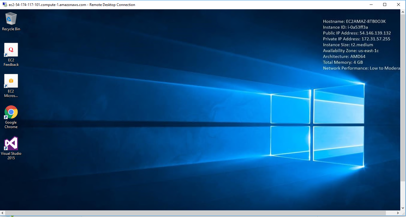
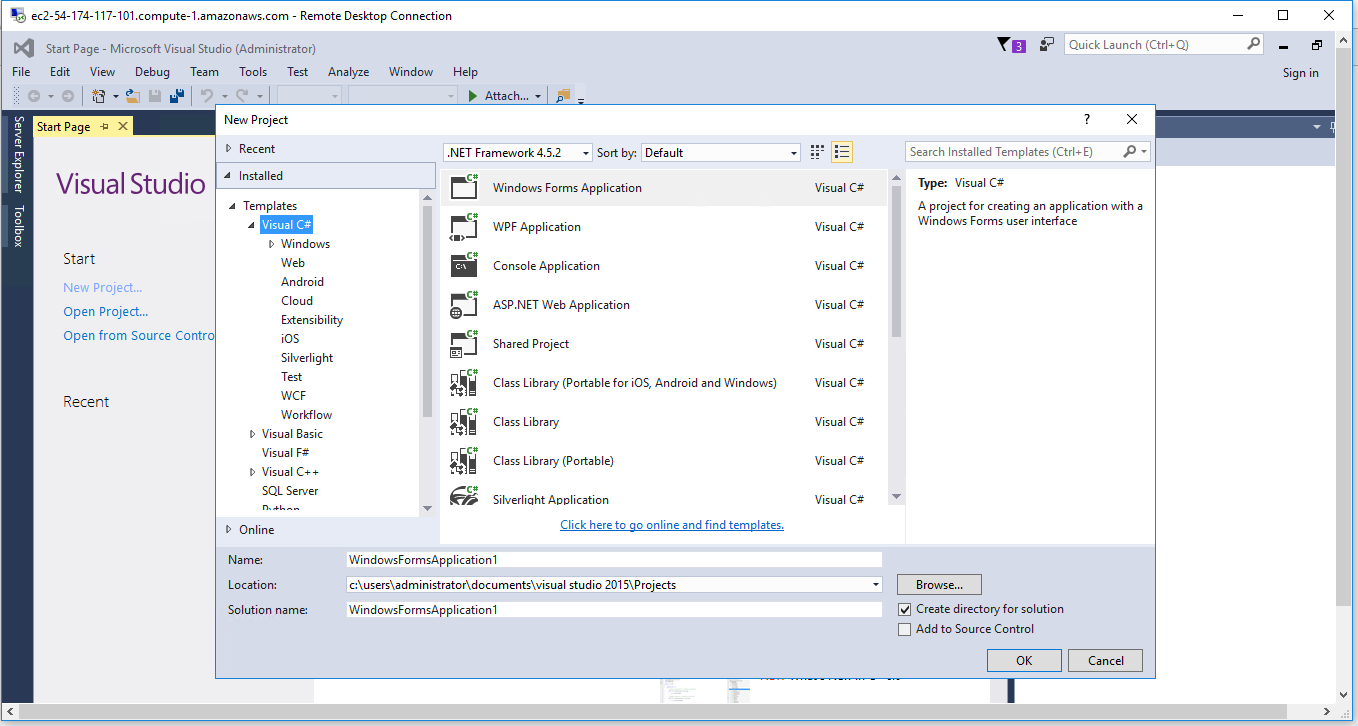
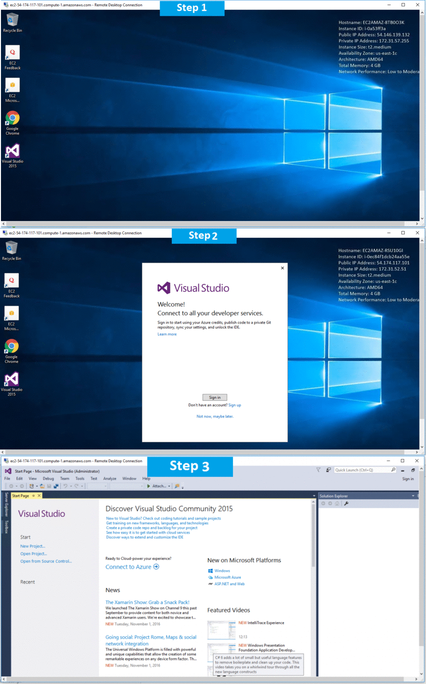
Step 1) RDP Connection: To connect to the deployed instance, Please follow Instructions to Connect to Windows instance on AWS Cloud
Connect to the virtual machine using following RDP credentials:
- Hostname: PublicDNS / IP of machine
- Port: 3389
Username: To connect to the operating system, use RDP and the username is Administrator.
Password: Please Click here to know how to get password
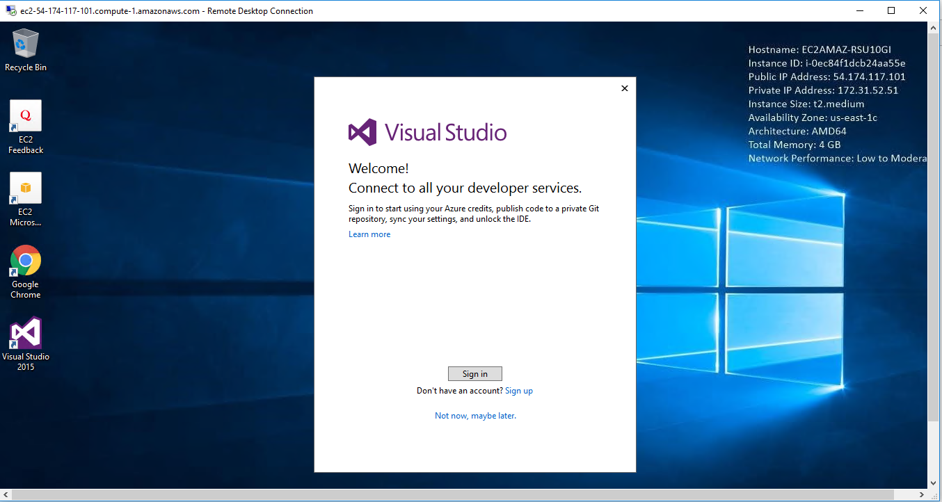
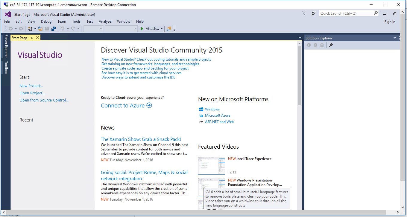
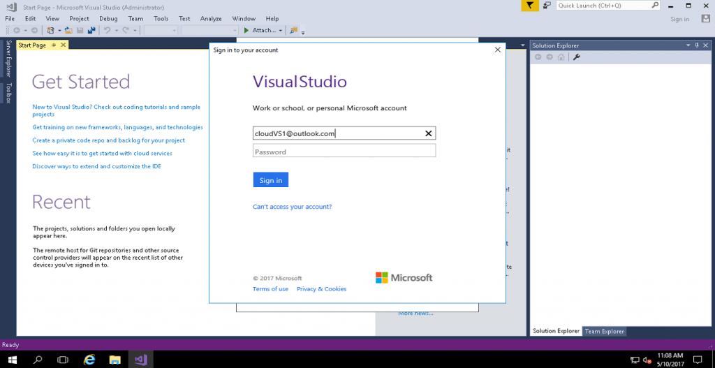
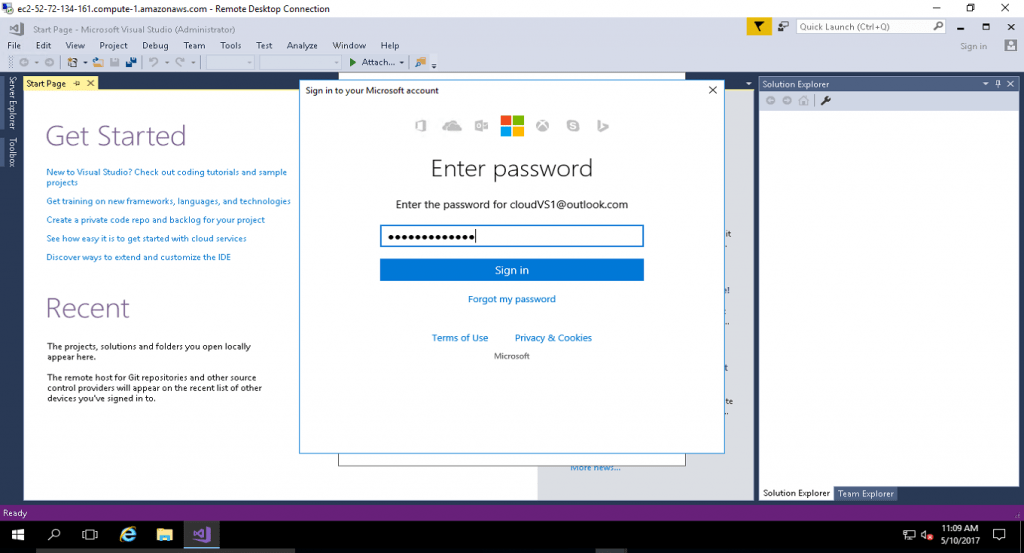
Step 2) Visual Studio Connection: To Connect Microsoft Visual Studio in windows server, Please follow Instructions to Connect Microsoft Visual Studio
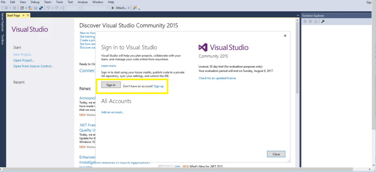
Note : Please use a Microsoft account to unlock the VS2015 IDE by signing in with your MS account.
Note that you may need to sign out and then sign in again.
You can sign up for MS account here if you do not have one.
Step 3) Other Information:
1.Default installation path: “C:\Program Files (x86)\Microsoft Visual Studio 14.0”
2.Default ports:
- Windows Machines: RDP Port – 3389
- Http: 80
- Https: 443
Configure custom inbound and outbound rules using this link
AWS Step By Step Sreenshots
Installation Instructions for Windows
Step 1) VM Creation:
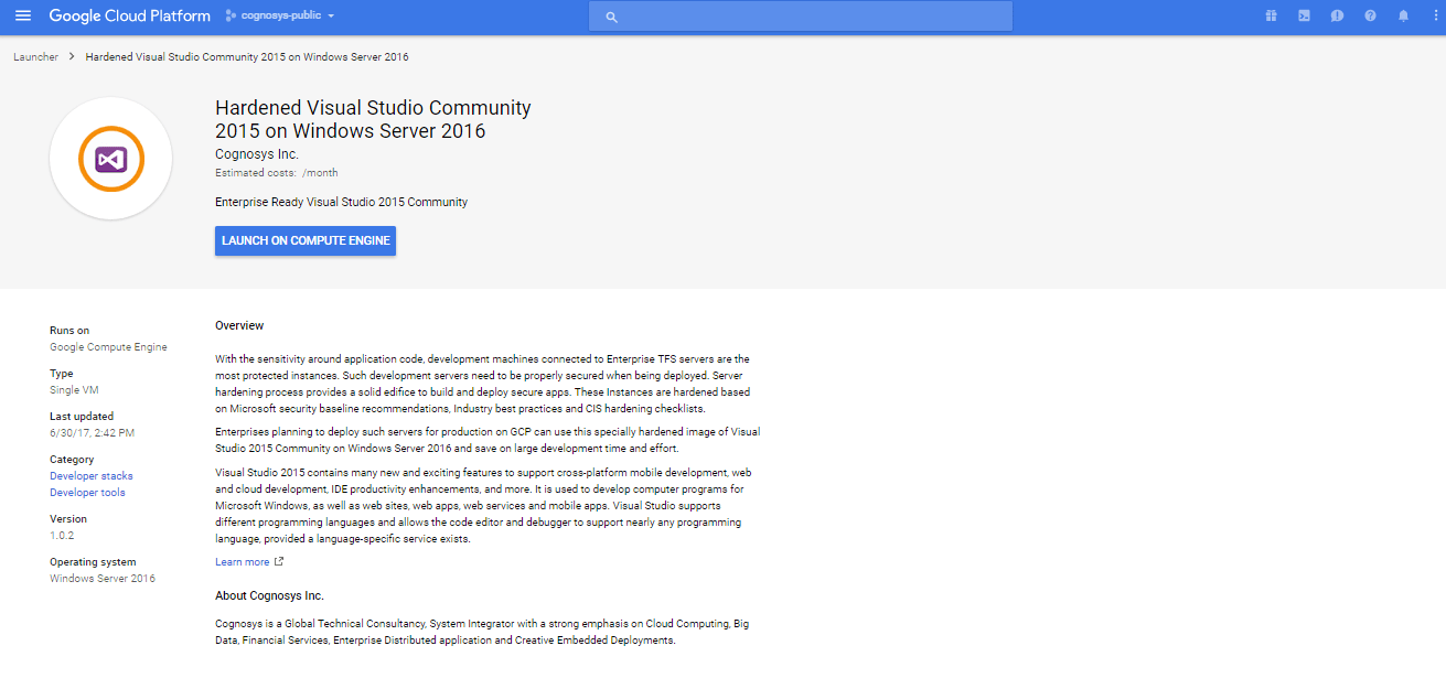
- Click the Launch on Compute Engine button to choose the hardware and network settings.
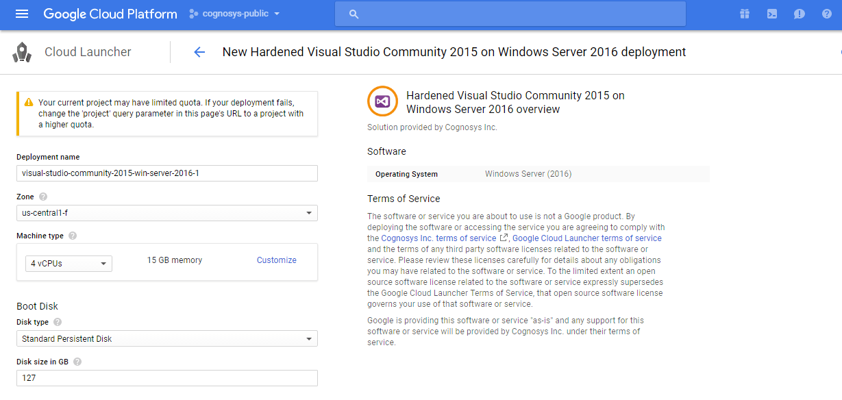
2.You can see at this page, overview of Cognosys Image as well as some estimated costs of VM.
3.In the settings page, you can choose the number of CPUs and amount of RAM, the disk size and type, etc.
Step 2) RDP Connection: To connect to the deployed instance, Please follow Instructions to Connect to Windows instance on Google Cloud
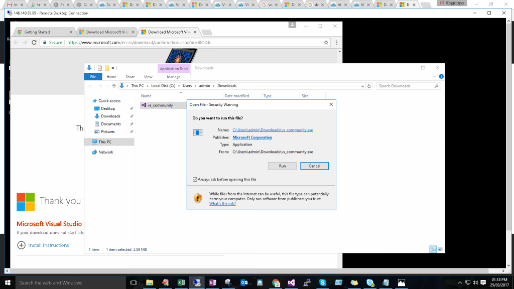
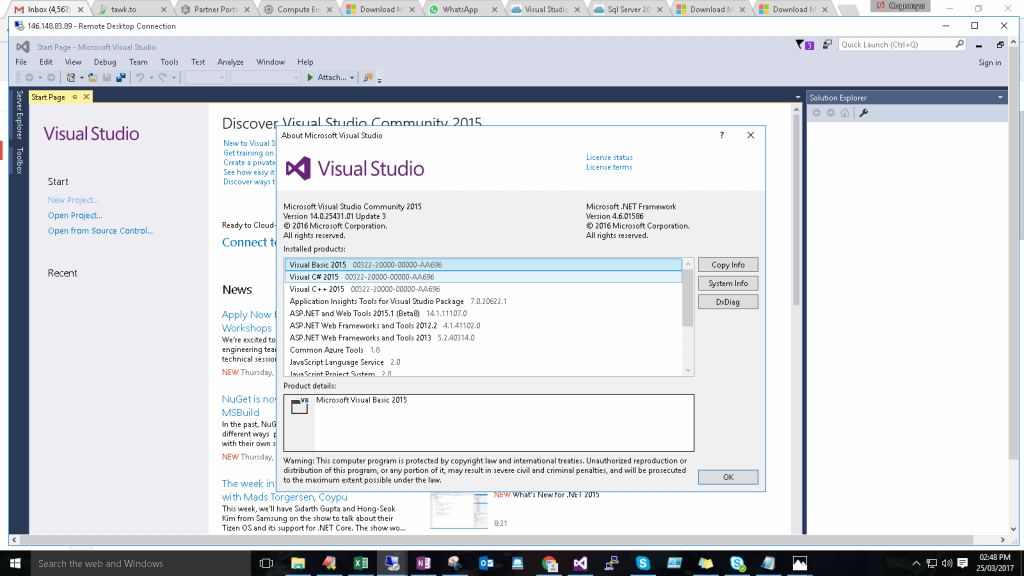
Step 3) Visual Studio Connection: To Connect Microsoft Visual Studio in Windows Server, Please follow Instructions to Connect Microsoft Visual Studio
Note: To activate Visual Studio community version kindly sign into your Visual Studio account with Microsoft ID.
Step 4) Other Information:
1.Default installation path: “C:\Program Files (x86)\Microsoft Visual Studio 14.0”
2.Default ports:
- Windows Machines: RDP Port – 3389
- Http: 80
- Https: 443
Google Step By Step Screenshots
Videos
Secured Visual Studio Community 2015 on Windows 2012 R2

