1-click AWS Deployment 1-click Azure Deployment
Overview
TinyCAD is a program for drawing electrical circuit diagrams commonly known as schematic drawings. It supports standard and custom symbol libraries. It supports PCB layout programs with several netlist formats and can also produce SPICE simulation netlists. It is also often used to draw one-line diagrams, block diagrams, and presentation drawings.
TinyCAD is an open source schematic capture program. Use TinyCAD to draw your own circuit diagrams. You can lay out circuit diagrams using the supplied libraries. Alternatively, there is a component library editor built into TinyCAD – so you can easily create your own symbols. You may also find more libraries on the Yahoo group that other users have drawn for you. Once you have drawn your design, you can use the special functions to automatically add symbol references, check your design against rules of correctness and create a parts list.
TinyCAD can also export a net lists for import into PCB layout programs. Once you have your design you can copy and paste it into other packages such as Word (or better still OpenOffice). You may also print your design to any supported Windows printer. If your design is larger than a single page then it can be either scaled to fit on a single page or printed across many pages. You can get the latest news, release and source code from the SourceForge site. Go to http://tinycad.sourceforge.net. The TinyCAD SVN source code and web site repository is located at https://tinycad.svn.sourceforge.net/svnroot/tinycad. If you are unfamiliar with SVN, you may find
TortoiseSVN (www.tortoisesvn.net) to be a good place to start.
Get To Work On Electric Circuits Freely And Easily.
Easier than it looks
Compared to other CAD programs, TinyCAD has an interface that’s about as busy but a number of tools that work more intuitively for beginning and intermediate CAD program users. It allows users to make their own libraries of symbols, which comes highly recommended, especially because the default symbols don’t look amazing. It’s the program’s greatest feature, even though libraries don’t update dynamically (when symbols are changed). TinyCAD is largely feature-complete, though it’s missing a few advanced netlist features, among others.
A Tiny Choice
Both pre-existing CAD users and those looking for a way to start designing electric circuits may find TinyCAD useful. Although the help files aren’t perfectly written or updated, and won’t help with some of the program’s more advanced and complex functions, the program itself is easy enough to start with that relative newbies will appreciate it.
TinyCAD for Schematic Drawing
TinyCAD is a program for drawing circuit diagrams commonly known as schematic drawings. It supports standard and custom symbol libraries. It supports PCB layout programs with several netlist formats and can also produce SPICE simulation netlists.
TinyCAD is an open source schematic capture program for MS Windows.
Use TinyCAD to produce professional circuit diagrams and export net list information to PCB applications.

TinyCAD is my preferred schematic capture program. This is entirely a personal preference and doesn’t match the preferences as a whole of the ‘Maker’ community, professional engineers or sane people. That being said I have a process that allows me to make things and TinyCAD is a part of it. If you want to make things like I do then follow these steps to get on your way.
Installation
TinyCAD is hosted on SourceForge so it’s always easy to get the latest version:
TinyCAD Latest Version Download Page
Note to Windows Vista users and above: As of December 2009 (and for reference I’m writing this in January 2013 so it may be fixed – I have no Vista or above to test it out) TinyCAD had issues regarding new user permissions when running as a User rather than Administrator in Windows Vista and above. This is mainly due to the location in which TinyCAD by default chooses to store its library files. If you follow this guide you will download a different set of libraries and install them to a different location in a directory where Users have the correct permissions. If you don’t download these libraries please move the TinyCAD default libraries from the Program Files\TinyCAD\library to a location under My Documnets or another folder a User will have full permissions to.
Note to Windows 8 users: As of December 2012 there was an issue with TinyCAD version 2.80.05 build 619 on Windows 8 where users would be unable to open and save files except by dragging the files onto the TinyCAD application and using Save As instead of Save. As far as I know these issues may be ongoing and Windows 8 is not the best operating system on which to run TinyCAD.
The installer is self-extracting and will pretty much install itself once you run it. You’ll get several screens:
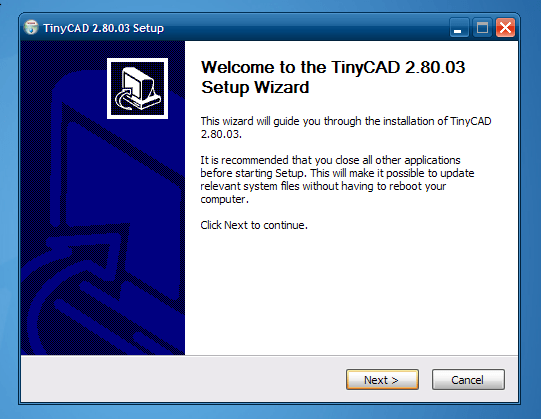
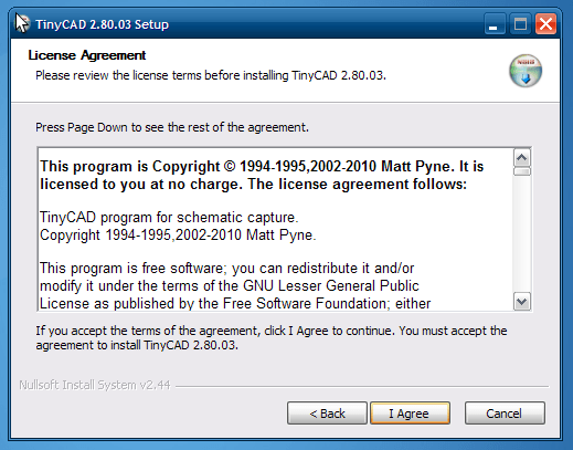
Clicking Next will take you to this screen where you agree to the license (GPL v2 I believe):
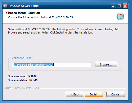
Then all you have to do is select the installation directory – the default should be fine but read the note above if you have any Windows above XP.
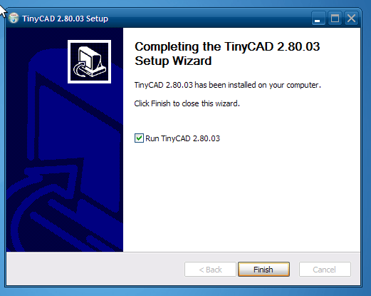
The actual installation takes almost no time on my computer. Then it asks if you want to run TinyCAD:
Library Installation
You can start to use TinyCAD with the default libraries or you can download the latest version of the libraries that I use. TinyCAD by default ships with a rather old set of disorganized libraries combined with a new set of more organized libraries. Ideally they would choose one or the other but such is life. The newer, more organized set of libraries can be downloaded by themselves from Github:
Alternate TinyCAD Libraries
I prefer to download this set of libraries and use only them, but it’s a matter of preference. Most people rely on making their own symbols anyhow.
If you click on that link it will download the whole repository containing the TinyCAD libraries. The actual libraries are stored in a subdirectory of the ZIP file: \Libraries\TCLib
This directory contains many .TCLib files. Create a new directory under My Documents – call it something like TinyCAD Libraries. Copy all of the .TCLib files there.
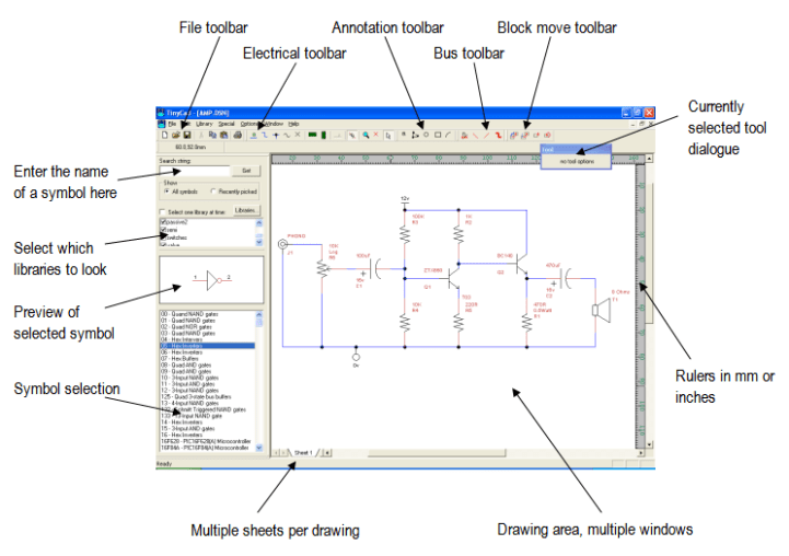
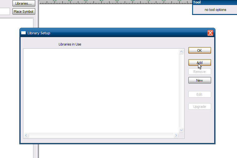
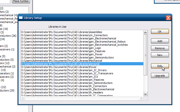
Now you need to add all of these new libraries to TinyCAD and remove the old ones. Start up TinyCAD and you should see a screen like this:

The mouse pointer is centered on the Libraries button – click it to open this dialog:
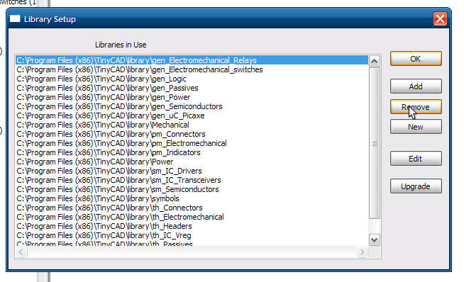
You’ll have to manually remove each library that’s in the dialog – yep, one at a time. Select, then Remove, then select, then Remove. Do this until the whole library dialog is empty:
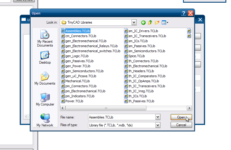
Now you can start adding the libraries in your My Documents\TinyCAD Libraries folder:
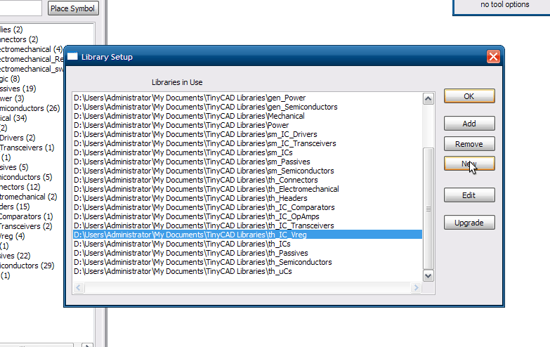
And continue until you’ve added all of them or as many of them as you want.
Parts Development
More often than not you’ll find that a part you need doesn’t exist in the libraries. This is regrettable but normal – even if you have a ‘real’ engineering job you’ll find that this is often the case. Drawing your own symbols is a necessary part of schematic capture.
Library Generation
You should in general add all new symbols to one library – your personal library. Alternatively you can try to organize all of symbols into logical groups. For example in the alternate TinyCAD libraries discussed above the library organization falls into a Type/Group/Part organization. For example the sm_IC_Transceivers.TCLib is Surface Mount (sm) / Integrated Circuit (IC) / Transceivers, gen_Passives.TCLib is Generic (gen) / Passives. This is the group for passive devices like resistors and capacitors and inductors that are not specifically through hole or surface-mount parts – just schematic symbols.
You can attempt an organization like that but I would recommend just using a single library for all of the parts you generate – until it becomes too large and difficult to organize.
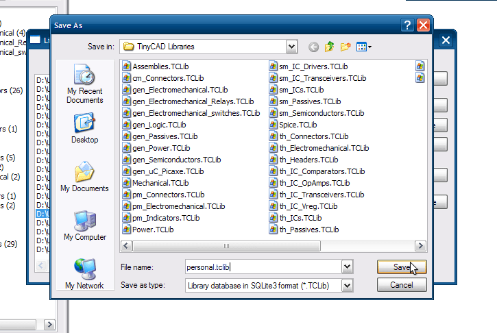
In TinyCAD open up the Libraries dialog and click on New:
You’ll be prompted to enter a name and location for your personal library. Call it whatever you like and put it in the same directory as the other library files:
Now your library shows up in the list of libraries in TinyCAD.
New Part Generation
Select your new library and click on the Edit button:
This will bring up a largely blank screen – your library is empty. Right-click on the blank space and select New Symbol in the menu:
A drawing canvas will come up. This is where you will draw the part. Before you start some settings have to be changed to save grief later on in the process. On the menu bar select Options->Settings:
The Settings dialog will open. The settings we’re interested in are:
- Show the Grid: On
- Snap to Grid: On
- Grid Spacing: Fine
Here is what the dialog should look like before you hit OK:
These grid settings will help ensure that the pins on the symbol you generate end up on the grid when you use them in a design. This is a very important step! You’ll be terribly frustrated if you don’t do this!
Now you can start drawing your part. There are three types of things you can have on the canvas when generating a part:
- Polygons/Lines – These are what you use to draw the part. TinyCAD supports arcs, circles, rectangles and generic closed polygons. Polygons can be filled with a variety of colors or patterns for flavor. Both polygons, lines and arcs allow line width, color and pattern can also be customized.
- Text – Generic text with support for multiple fonts, styles (bold, italics, etc.), sizes and text directions
- Pins – Pins are the most important aspect of generating a part because they are used in the netlists which dictate board layout and SPICE models among other things.
The most attention in this tutorial will be paid to the pins. The other graphical options can improve the visual aspects of the part but if the pins are wrong that isn’t worth very much. Feel free to investigate the myriad graphical options on your own with the knowledge that the worst you can do is make the part uglier.
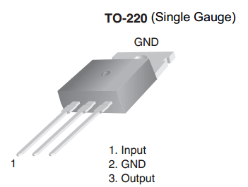
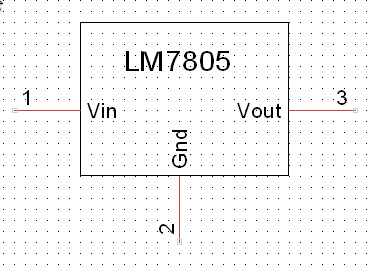
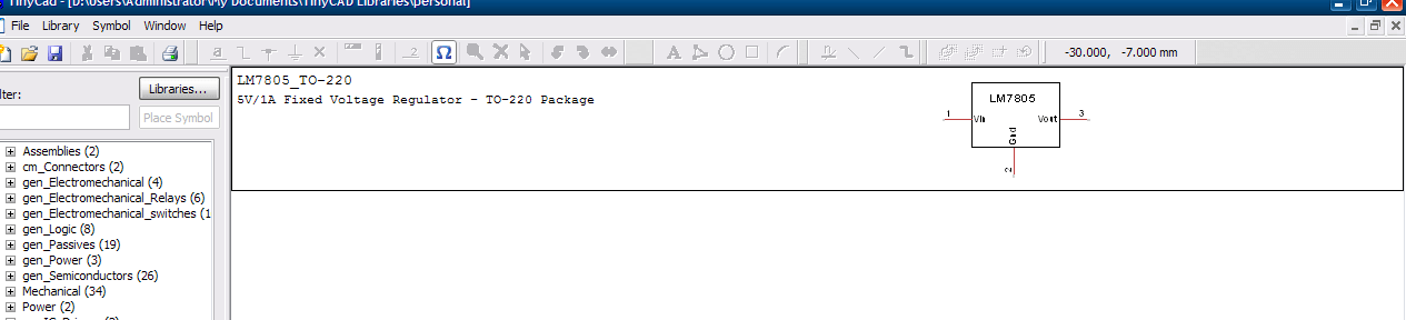
The part that I will create in this tutorial is the LM7805 TO-220 Package 5V Voltage Regulator. The first place to start the datasheet. The datasheet will provide you an example symbol and the pinouts for the package you intend to use. It is very important to use the correct pinout! Datasheets often cover multiple packages for the same part. For example, note the differences in pinouts for the various packages of the ATMega328P:
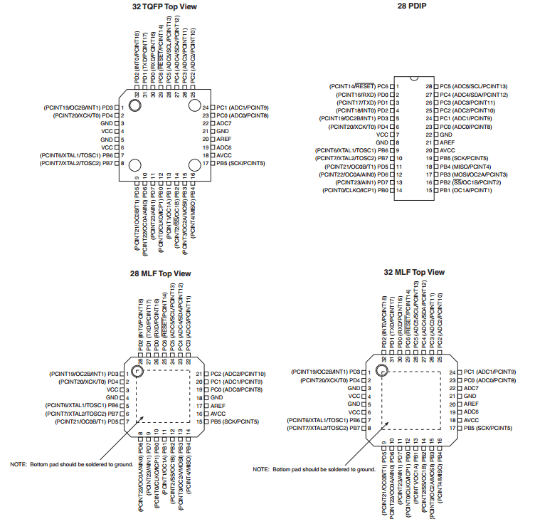
A lot of packages look the same! It’s easy to get confused between an SSOP package and a PDIP package on a datasheet, so don’t get fooled.
The LM7805 datasheet luckily has only one pinout:
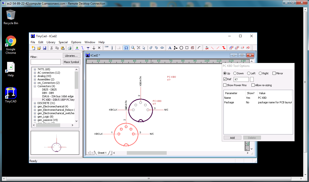
And later in the document they show several circuits which include a schematic symbol for the LM7805:
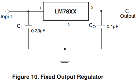
It’s nothing fancy but it will do – let’s reproduce it in TinyCAD.
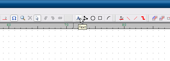
At this point we’re still on the canvas screen where we can start drawing. Since we’re just going to reproduce the datasheet, let’s start by adding in the ‘LM7805’ text that will go in the symbol. Click on the text icon on the toolbar:
The text toolbox comes up. Type ‘LM7805’ into it:
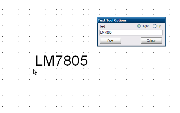
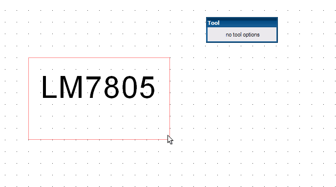
Then click the mouse somewhere in the canvas to place the text. Next we need to draw a box around the text, so click the rectangle button from the toolbar:
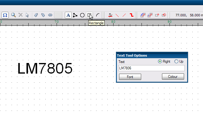
And draw an appropriately-sized rectangle around the text:
Now it’s time for the pins. From the datasheet, the pinout was:
- Vin/Input Voltage
- Gnd/Ground
- Vout/Output Voltage
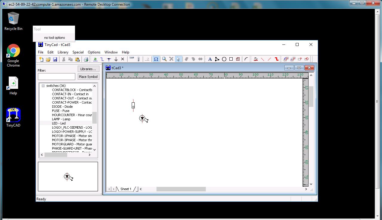
Start by clicking the pin button on the toolbar:
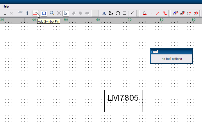
This brings up the pin toolbox where we’ll put in the information for pin 1:
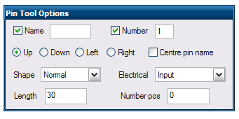
There are a lot of options here and this is one of the important steps, so I’ll go through the options and their significance in order of importance:
- Number – This is the most important! If this isn’t correct then your board layout may suffer. I’ve had to deal with mis-numbered pins which caused my layouts to be incorrect. This mean a whole board was essentially worthless. Bottom line: do not screw up your pin numbers!
- Name – Important to help you keep everything straight. If you accidentally switch two pin names you’ll be very confused.
- Up/Down/Left/Right – You want to get this right so that your pin is facing the correct direction. The rule of thumb is that the wire connection point faces the opposite of the chosen direction. So if you select Up the connection point for the pin will be on the bottom of the pin, Left means the connection point is on the right, etc.
- Electrical – This information is used by TinyCAD to perform Design Rule Checks. While it is not strictly necessary to use this field the DRC is actually rather useful. Most of the options here are used for digital circuits: Input, Output, Tristate and Input/Output are only useful for digital circuits. Passive is useful for analog/passive components such as resistors and capacitors and power pins on digital ICs, but also for things like the LM7805 which has pins that don’t really fit into any other category. Open Collector is useful for ICs that have open collector outputs like the ULN2803. No Connect could be used anywhere – many ICs specify No Connect for some pins. As always, consult your part’s datasheet for specifics.
- Shape – This is mainly a beautification tool. Some pins (clock pins for example) have an alternate pin style drawn in the datasheet. It’s nice to copy this and TinyCAD has a large selection of styles to mimic the styles shown in datasheets.
- Length – Largely a style decision but take not that some oddball lengths can cause pins to not sit on the grid and will prevent you from connecting to the part. I usually go with 15 or 30.
- Centre pin name – You can do this if you want. I prefer pin names inside the symbol so I leave it unchecked.
- Number pos – This only moves the position of the text which indicates the pin number. Move it if you want.
Using the pinout from the datasheet I added all three pins as they were shown in the datasheet. All were 30 length and Passive typed pins. I had to increase the size of the rectangle to accommodate the text for the pin names and it ended up looking like this:
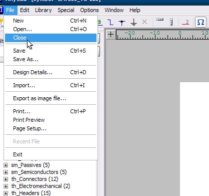
Now we’re done! Go to the menu bar and select File->Close:
This will force a save and bring up the save dialog which you can see below.
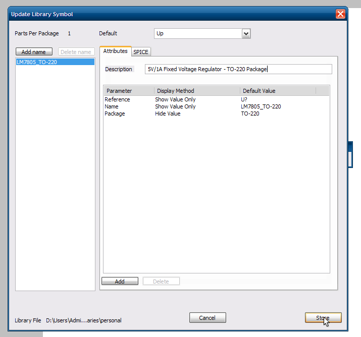
This dialog has several important parts:
- Description – Definitely put something here. I like to put the description of what the part does and its package in case I have multiple package types for this part.
- Reference – You can set this to any number of this – U? is somewhat generic. Usually resistors will be R?, capacitors are C?, etc. Make sure to include ? – this gets replaced by the reference designation number for a specific instance of this part.
- Name – I like it to include the part name and package
- Package – This is a necessary parameter to set but it’s difficult to say what it should be. It is dependent on your board layout tool. The package you put here has to be understood and supported by your board layout tool. I’ll discuss this more when I write the guide for FreePCB. In general, put the package name in here if you don’t know.
You can also add as many parameters as you like. I tend to add things like Digi-Key part number, price per unit, electrical characteristics and so forth. Two important parameters to add for some components (such as capacitors and resistors) are Value and Tolerance.
This is the completed dialog for the LM7805 with me ready to Store the part in the library:
When the dialog clears you’ll see your library is no longer empty:
You’ve just made your first part!
Schematic Capture
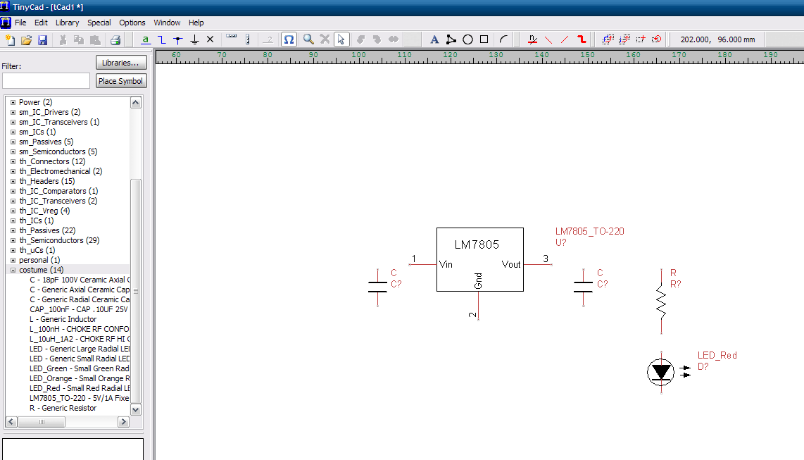
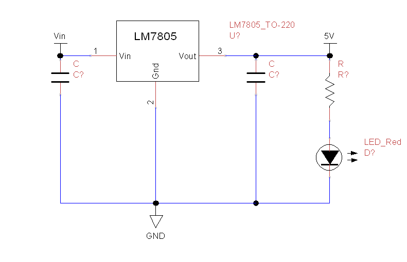
TinyCAD makes it easy to capture schematics quickly. The schematic I’ll show you how to create is a typical 5V source using an LM7805. We’ll follow the schematic provided in the LM7805 datasheet:

However, I’m also going to add an LED that will light when the 5V source is on. I’ll discuss adding that in a minute.
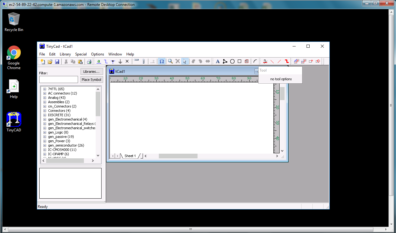
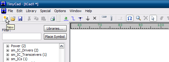
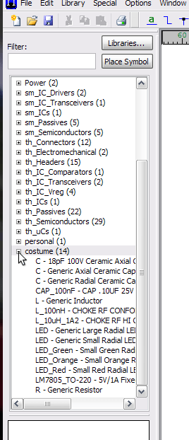
Since I’ve already written up how to create libraries and parts I’ve provided all of the parts necessary to generate this schematic in a library on Github. Just download and add the costume.TCLib library to TinyCAD as per the instructions above. Next, in TinyCAD click on the New button in the toolbar:
A blank canvas will appear where we can place all of our parts. Open up the costume library and you’ll see all the parts we’re going to use:
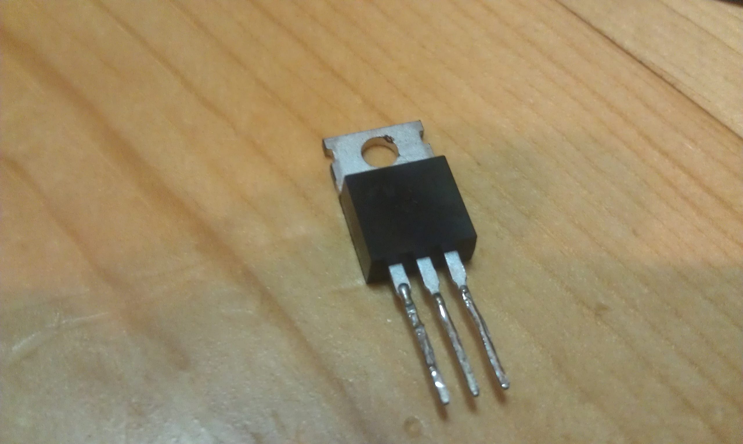
1x LM7805_TO-220 – We can’t get by without having the 5V regulator. The TO-220 package can handle 1A of current. The actual part looks like this:
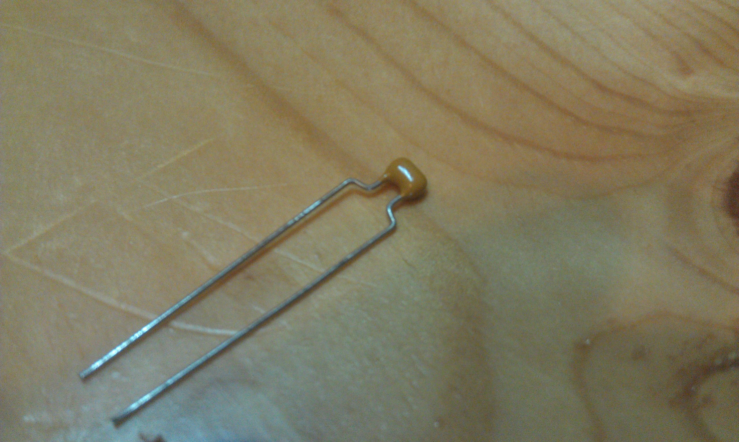
2x C – Generic Radial Ceramic Capacitor – The datasheet doesn’t specify any special type of capacitor and I have some ceramic radial through-holes on hand, so I went with this rather than the axial. They look like this:
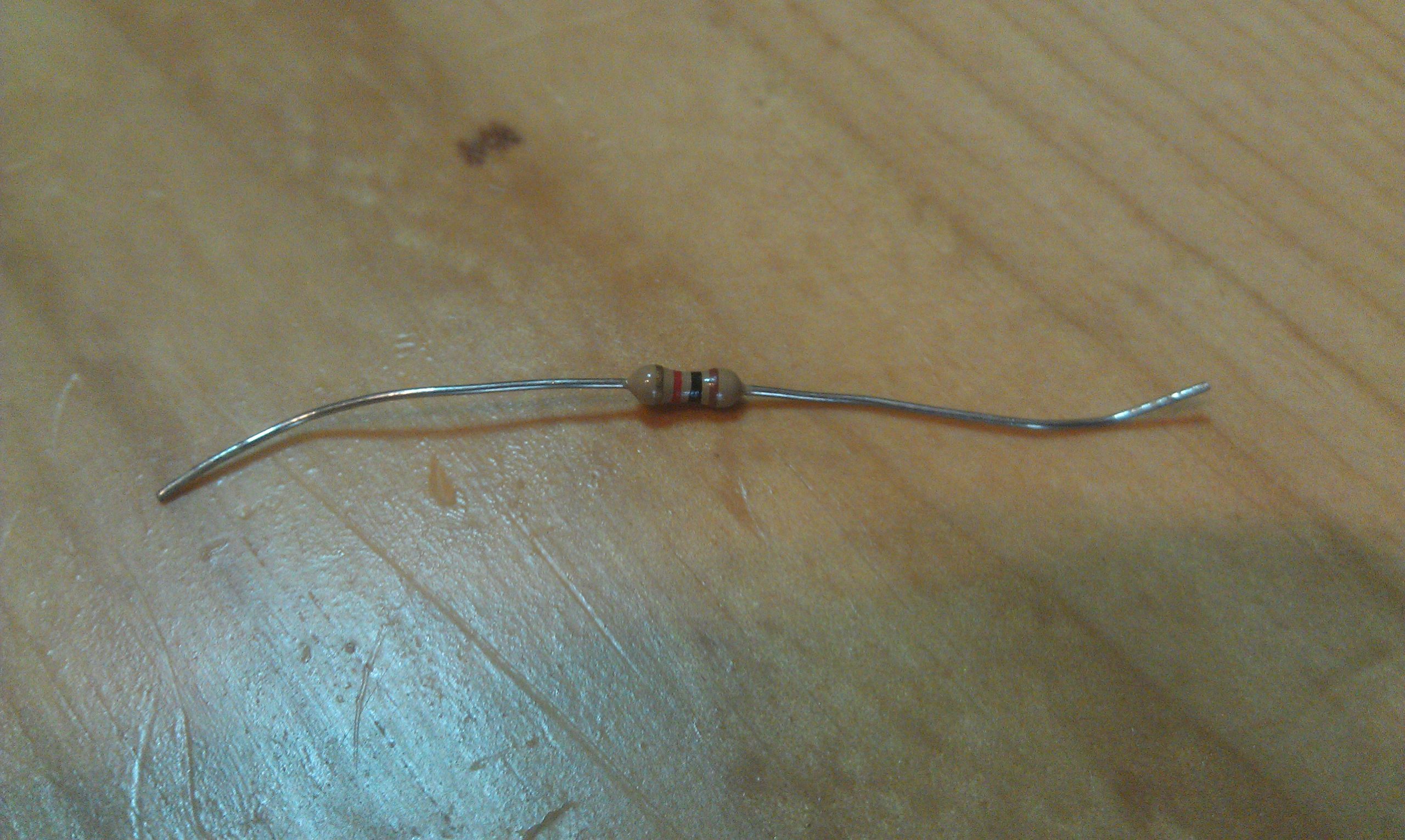
1x R – Generic Resistor – A generic through-hole radial resistor to bias the LED. You’ve probably seen this before:
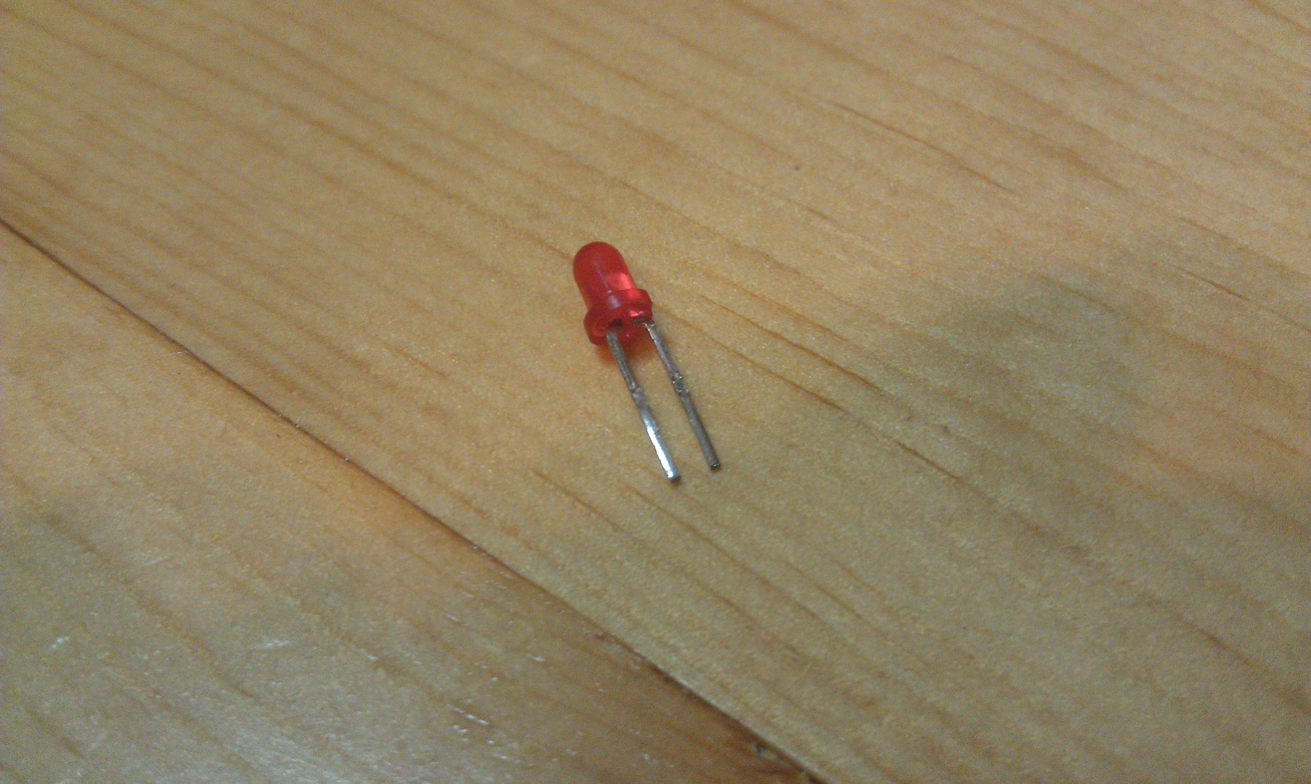
 1x T-1 sized LED – Maybe it’s from Radio Shack, maybe it’s from an overstock house. Here’s an example:
With everything placed on the canvas it should look roughly like this:
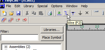
Now you have to draw the connections between the components as they are in the circuit. Click the Wire button on the toolbar:
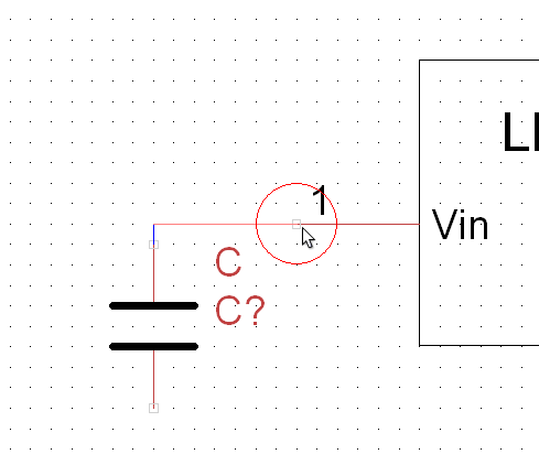
Then, move the cursor to a pin and notice the connection bubble show:
Click on the pin and it will start a wire (also called a net) – connect it to the input of the 7805:
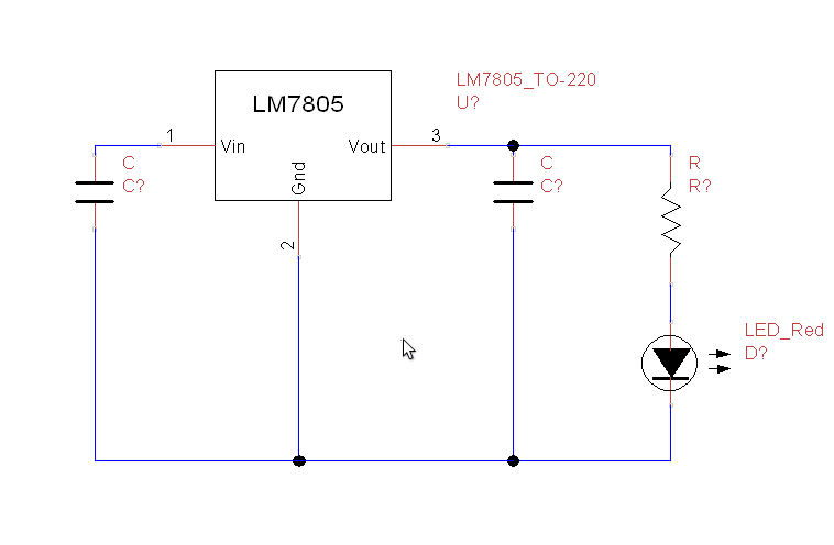
Then add the rest of the connections. It will look like this in the end:
Now I’m going to add power connections. The power connections allow you to connect different nets together by adding the power connection to the net. The ground symbol is an example – every ground is tied together. This goes strictly by name – all nets connected to a GND power connection will be considered to be connected for the purposes of the schematic. Also, they make the schematic look cool. Click on the Power icon in the toolbar:
This brings up the Power dialog where you can choose for power symbols:
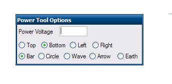
I use the following symbols:
- GND – Arrow/Down
- 5V – Top/Bar
- Vin – Top/Bar
The end result looks like this:
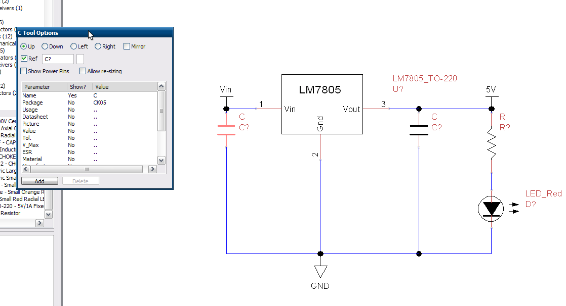
The next step is to put values on the capacitors and resistors. Click on the left-most capacitor – the Properties dialog shows up:
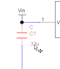
Edit the Value field to a value of ‘.33u’ – 33 micro-farads – and set the Show? tag to ‘True’ so that the value will show up on the schematic – the Properties window looks like this afterwards:

When the Value field is set to visible it pops up a bit far away from the capacitor, so I move it:
Then I repeat the process for the other capacitor. As for the resistor value I just chose a value of 1K. This will give the LED a few mA of current which should at least light it up but shouldn’t suck up too much current. Doing some quick calculations and assuming a forward LED voltage of 1.7V: 5V -1.7V = 3.3V/1K = 3.3mA. So it should light but not much – this is desirable for a power LED. All the values added look like this:
Now that all the components are placed and the values set we have to update the symbol references. Right now the symbol references are unset: they all say D? instead of D1. TinyCAD can automatically set all of the references. Start by clicking on the Special->Generate Symbol References. This dialog will show up:
The default settings are fine. Click on OK and all of the symbol references will be generated and added – no more D? but instead D1. The only thing left now is to save it. Click on the Save button on the toolbar:
And then save it wherever you want (I’ll discuss project organization later):
And that’s it – you’ve capture your first circuit!
TinyCAD Mesh Tools
The add-on is a combination of several scripts which should be useful to anyone who has used other CAD software for drafting with some level of precision. The context menu has the tinyCAD functions prepended to it.
Activation
- Open Blender and go to Preferences then the Add-ons tab.
- Click Mesh then tinyCAD Mesh tools to enable the script.
Description
VTX
Automatically extends, projects or intersects the two selected edges if they are co-planar. For auto VTX you must be in (Edit Mode and edge mode) and have two edges selected. When invoked the add-on will detect if you are trying to intersect, project or extend two edges. It will internally pick from V, T or X. It will also notify you if the edge are not co-planar / do not intersect.
- V: Extending two edges towards their calculated intersection point.
- T: Extending the path of one edge towards another edge.
- X: Two edges intersect, their intersection gets a weld vertex. You now have four edges and five vertices.
XALL
This mass intersects a collection of edges. Pick a collection of edges and invoke XALL. It will deselect any edge that doesn’t intersect other edges first. Then it goes through all combinations of the remaining edges to see if there are intersections. Each intersection is dealt with and the result is added to the collection of edges to check. This process continues until no more intersections are found.
BIX
Given two selected edges, this script creates the bisector of these edges. The edges are first checked for co-planarity.
CCEN
Construct a circle and its center. Pick three vertices that once made up a circle, then , the script adds a Grease Pencil representation of the circle. To add a mesh of that constructed circle you can press F6 straight afterwards and adjust the circle’s vertex count. Then press Make Circle Mesh to add a new circle. This is a little bit experimental, but works fine.
TinyCAD is owned by TinyCAD (https://www.tinycad.net/) and they own all related trademarks and IP rights for this software.
TinyCAD on cloud for AWS
Features
Major Features of TinyCAD
-
- Flat or Hierarchical Schematic Entry
- Many popular PCB Layout compatible netlist formats
- Convenient support for embedding graphical images in drawings
- Small install (5mb)
- Very intuitive and easy to use
- Good design checker (to pick up those human errors)
- Ability to generate netlists (in multiple formats include those used by Freepcb), parts lists and export designs as images.
- very easy to create new components and add them to the component library
- Good support forum
- Runs on linux under wine
AWS
Installation Instructions For Windows
Note: How to find PublicDNS in AWS
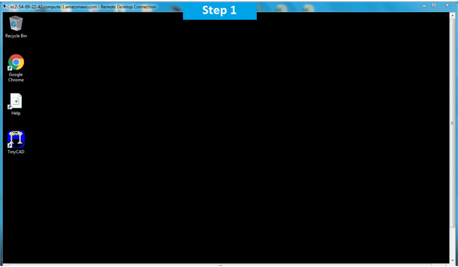
Step 1) RDP Connection: To connect to the deployed instance, Please follow Instructions to Connect to Windows instance on AWS Cloud
1) Connect to the virtual machine using following RDP credentials:
- Hostname: PublicDNS / IP of machine
- Port : 3389
Username: To connect to the operating system, use RDP and the username is Administrator.
Password: Please Click here to know how to get password .
Step 2) Click the Windows “Start” button and select “All Programs” and then point to TinyCAD.
Step 3) Other Information:
1.Default installation path: will be in your root folder “C:\Program Files (x86)\TinyCAD”
2.Default ports:
- Windows Machines: RDP Port – 3389
- Http: 80
- Https: 443
Note: Click on Desktop icon – Press start then App will open in browser.
Configure custom inbound and outbound rules using this link
Step by Step Installation Screenshots